
How to Install a Three Phase Voltage Stabilizer in Your Workshop

 Site Editor
If you are installing a three-phase servo voltage stabilizer in a workshop for the first time, the process involves five main stages: pre-installation preparation, mechanical placement, electrical wiring, startup and commissioning, and operational verification. Following a structured sequence reduces the risk of wiring errors, equipment damage, and unsafe conditions. This guide walks through each step based on the typical setup of a TNS-series three-phase automatic voltage stabilizer—a common choice for workshops with industrial machinery, CNC equipment, or motor-driven systems.
Before You Start: What You Need to Know
The TNS series three-phase stabilizer is a high-accuracy automatic AC voltage stabilizer designed for three-phase four-wire systems. It accepts an input voltage range of 280–450V and delivers a regulated output of 380V ± 3%. It is intended for workshops and industrial environments where power-driven equipment requires stable voltage to operate reliably.
Before beginning installation, confirm the following:
- Input power is turned off at the main distribution board
- The stabilizer rating matches your load requirements (available from 1.5 kVA to 50 kVA)
- The installation area is clean, dry, and well-ventilated
- Qualified personnel will perform the electrical connections
Pre-Installation Preparation
Proper preparation prevents most installation problems.
Unpack and Inspect
- Remove the stabilizer from its packaging carefully. Keep the packaging materials for future transport if needed.
- Check for any visible damage that may have occurred during shipping.
- Verify that all components are present—check against the packing list.
- Locate the user manual and keep it accessible for reference.
Verify Site Conditions
The installation location must meet these conditions:
| Requirement | Specification |
|---|---|
| Ambient temperature | -5°C to +40°C |
| Relative humidity | Below 90% |
| Ventilation | Adequate airflow; avoid enclosed cabinets without ventilation |
| Floor surface | Flat and able to support the unit's weight |
| Clearance | Minimum space for front panel access and rear ventilation |
Avoid locations with excessive dust, moisture, corrosive gases, or direct sunlight exposure.
Gather Tools and Materials
- Copper lugs and power cables
- Screwdrivers and wrenches for terminal connections
- Multimeter or voltage tester
- Personal protective equipment
Mechanical Installation
Position the Stabilizer
- Place the stabilizer on a firm, level surface. Use anti-vibration pads if the floor transmits vibration from nearby machinery.
- Ensure the unit is stable and will not shift during operation.
- Allow adequate clearance behind the unit for ventilation and cable entry.
- Position the front panel for easy access during operation and maintenance.
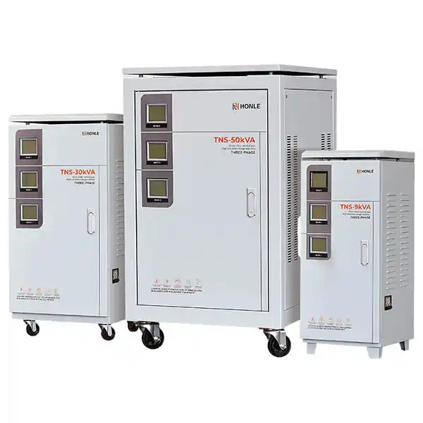
TNS units are typically floor-mounted. For larger ratings, the unit may be heavier and require mechanical lifting equipment.
Electrical Wiring
Important: All electrical work must be performed by qualified personnel. Ensure the input power supply is disconnected before making any connections.
Identify the Terminals
The TNS series three-phase stabilizer uses a three-phase four-wire system. The input and output terminals are typically marked as:
- Input: L1, L2, L3, N (neutral)
- Output: L1', L2', L3', N' (neutral)
- Earth (PE): Dedicated grounding terminal
Connect the Input Supply
- Connect the incoming three-phase supply from the main distribution board to the input terminals (L1, L2, L3).
- Connect the neutral wire to the input N terminal. The neutral wire must be connected at the input for proper operation.
- Connect the earth/ground wire to the PE terminal.
- Ensure all connections are tight and secure. Loose connections can cause overheating and voltage instability.
Connect the Output Load
- Connect the output terminals to the workshop equipment or sub-distribution panel.
- Connect the output neutral to the N' terminal.
- Connect the output earth/ground to the PE terminal.
- Verify that the rated voltage of the connected equipment matches the stabilizer's output voltage (380V).
Cable Sizing
Select cable sizes based on the stabilizer's rated current. For reference, the output current ranges from 2A (1.5 kVA) to 68A (50 kVA). Consult local electrical codes for specific cable sizing requirements.
Startup and Commissioning
Pre-Start Checks
Before applying power, verify:
- [ ] All input and output connections are secure
- [ ] Neutral and earth connections are properly made
- [ ] No tools or debris remain inside or near the unit
- [ ] The stabilizer's circuit breaker or disconnect switch is in the OFF position
- [ ] Load equipment is disconnected or turned off
Initial Power-Up
- Close the main input circuit breaker at the distribution board to supply power to the stabilizer.
- Turn on the stabilizer's input circuit breaker (if equipped).
- Observe the control panel indicators. The voltage meters should show the input voltage on each phase.
- The stabilizer will begin automatic voltage regulation. This may take a few seconds.
- After stabilization, check that the output voltage reads 380V ± 3% on each phase.
Verify Phase Balance
For three-phase systems, check that all three phases are balanced. The TNS series uses individual phase meters to indicate each phase independently. If one phase shows a significant deviation, verify the input connections and load distribution.
Connect the Load
- With the stabilizer running and output voltage confirmed, turn off the stabilizer output (if a separate output breaker is provided).
- Connect the workshop equipment or turn on the output distribution breakers.
- Turn the output back on and monitor the voltage as loads are added.
- Check that the voltage remains within specification under load.
Operational Verification
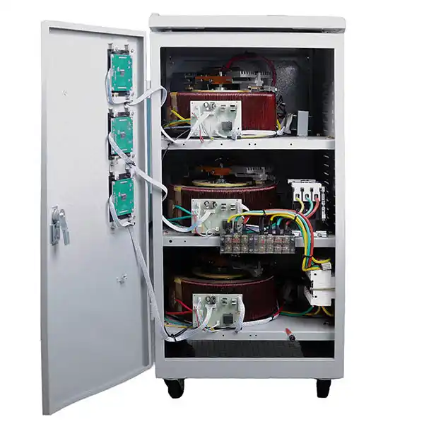
After the stabilizer is running with load:
- Monitor voltage on all three phases for 15–30 minutes under normal operating conditions.
- Check temperature—the unit should not exceed 70K temperature rise at full load.
- Listen for unusual noise—servo motor movement is normal, but grinding or excessive noise may indicate issues.
- Verify protection functions—confirm that over-voltage and time-delay protection features are operational.
Installation Checklist
Use this checklist to ensure no step is missed:
| Stage | Item | Completed |
|---|---|---|
| Preparation | Unit unpacked and inspected | [ ] |
| Site conditions verified (temp, humidity, ventilation) | [ ] | |
| Tools and materials gathered | [ ] | |
| Mechanical | Unit placed on level, stable surface | [ ] |
| Adequate clearance maintained | [ ] | |
| Wiring | Input L1, L2, L3 connected | [ ] |
| Input neutral connected | [ ] | |
| Earth/ground connected | [ ] | |
| Output L1', L2', L3' connected | [ ] | |
| Output neutral connected | [ ] | |
| All terminals tightened | [ ] | |
| Startup | Pre-start checks completed | [ ] |
| Input power applied | [ ] | |
| Output voltage verified (380V ± 3%) | [ ] | |
| Phase balance checked | [ ] | |
| Verification | Voltage monitored under load | [ ] |
| Temperature checked | [ ] | |
| Protection functions verified | [ ] |
Common Installation Mistakes to Avoid
| Mistake | Consequence | Prevention |
|---|---|---|
| Forgetting to connect neutral | Unstable regulation, possible damage | Double-check neutral connection at input |
| Undersized cables | Overheating, voltage drop | Size cables per current rating |
| Poor ventilation | Overheating, reduced service life | Maintain clearance around unit |
| Loose terminal connections | Arcing, intermittent operation | Torque all connections properly |
| Connecting load before stabilization | Equipment may receive unstable voltage | Wait for stabilization before connecting load |
FAQ
Q: Do I need a qualified electrician to install a three-phase voltage stabilizer?
Yes. Three-phase electrical work involves high voltage and significant current. Only qualified personnel with appropriate training and equipment should perform the installation.
Q: What happens if I forget to connect the neutral wire?
The stabilizer will not regulate properly. The TNS series requires a neutral connection at the input for the control circuit to function correctly. Operation without neutral can damage the unit or connected equipment.
Q: How long does it take for the stabilizer to start regulating after power is applied?
The TNS series includes a short delay of approximately 5 ± 2 seconds before the output is enabled. This delay allows the control circuit to stabilize before applying power to the load.
Q: Can I install the stabilizer outdoors?
No. The specified operating environment is indoor, dry, and ventilated. The ambient temperature range is -5°C to +40°C, and relative humidity should be below 90%. Outdoor installation exposes the unit to moisture and temperature extremes that exceed these specifications.
Q: How do I know if my workshop needs a 1.5 kVA or a 50 kVA unit?
Add up the total power consumption (in kVA or kW) of all equipment that will run simultaneously on the stabilizer. Choose a rating that exceeds this total by a safety margin. The TNS series is available from 1.5 kVA to 50 kVA. For specific sizing assistance, consult the technical specifications or contact the supplier.
Q: What maintenance does a servo voltage stabilizer need after installation?
Regular maintenance includes periodic inspection of carbon brushes, checking terminal tightness, cleaning ventilation openings, and verifying output voltage accuracy. The frequency depends on operating hours and environmental conditions.
Conclusion
Installing a three-phase servo voltage stabilizer in a workshop is a straightforward process when approached systematically: prepare the site, position the unit, complete the wiring, start up in sequence, and verify operation under load. The most critical steps are proper neutral connection, correct cable sizing, and thorough pre-start verification.
If you are still determining the right stabilizer rating or configuration for your workshop, review the available automatic voltage stabilizer models for specifications and capacity options. For specific applications or technical questions, contact the Honle engineering team for installation support and product selection guidance.