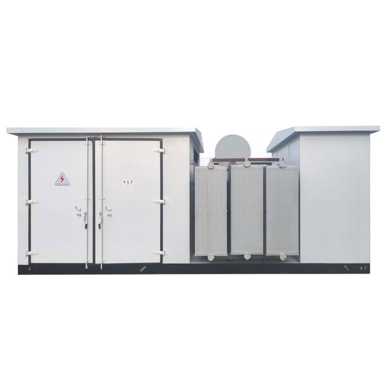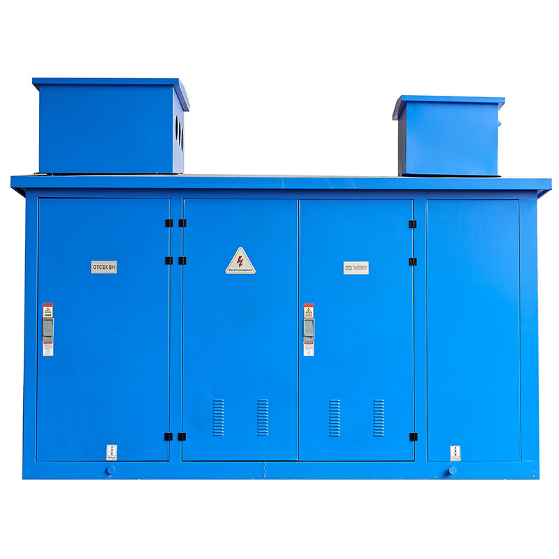
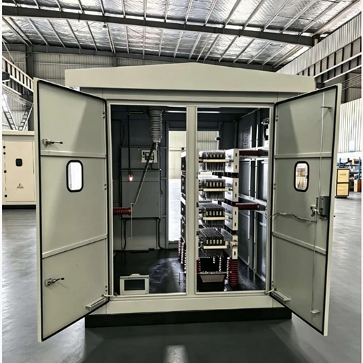
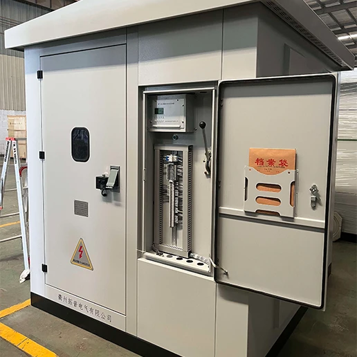
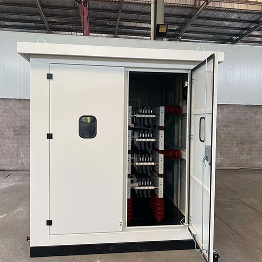
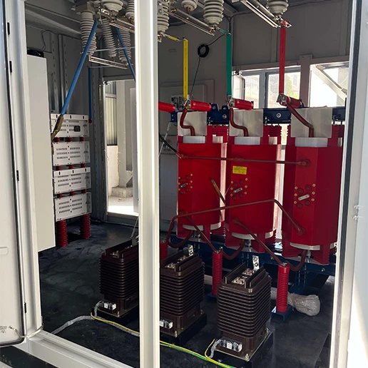

The HL-NGR series neutral grounding resistor devicesare mainly used in urban distribution networks below66 kV dominated by cable lines, large industrial parks,offshore platform power distribution systems, and im-portant power transmission and distribution systems inindustries such as iron and steel, petrochemical, airports,ports, and subways, as well as in power plant generatorsand auxiliary power systems.
The HL-NGR series neutral grounding resistor devices areindependently developed and manufactured by HonleGroup Co,Ltd, based on absorbing advanced foreigntechnologies and experience. They feature a uniquestructure and attractive appearance. The resistanceelements are made of special high-quality nickel-chro-mium stainless steel and other electrothermal alloy ma-terials dedicated for high-power resistors, offering excel-lent characteristics such as high resistivity, high tensile
strength, high oxidation resistance, high temperaturetolerance, low temperature coefficient of resistance, sta-ble resistance values, and long service life.
The principle of the neutral grounding resistor is to limitthe fault current through the instantaneous heat gen-eration and energy dissipation damping effect of theresistance elements, thereby limiting the system over-voltage level and achieving fast and accurate fault lineselection in the case of single-phase-to-ground faults.
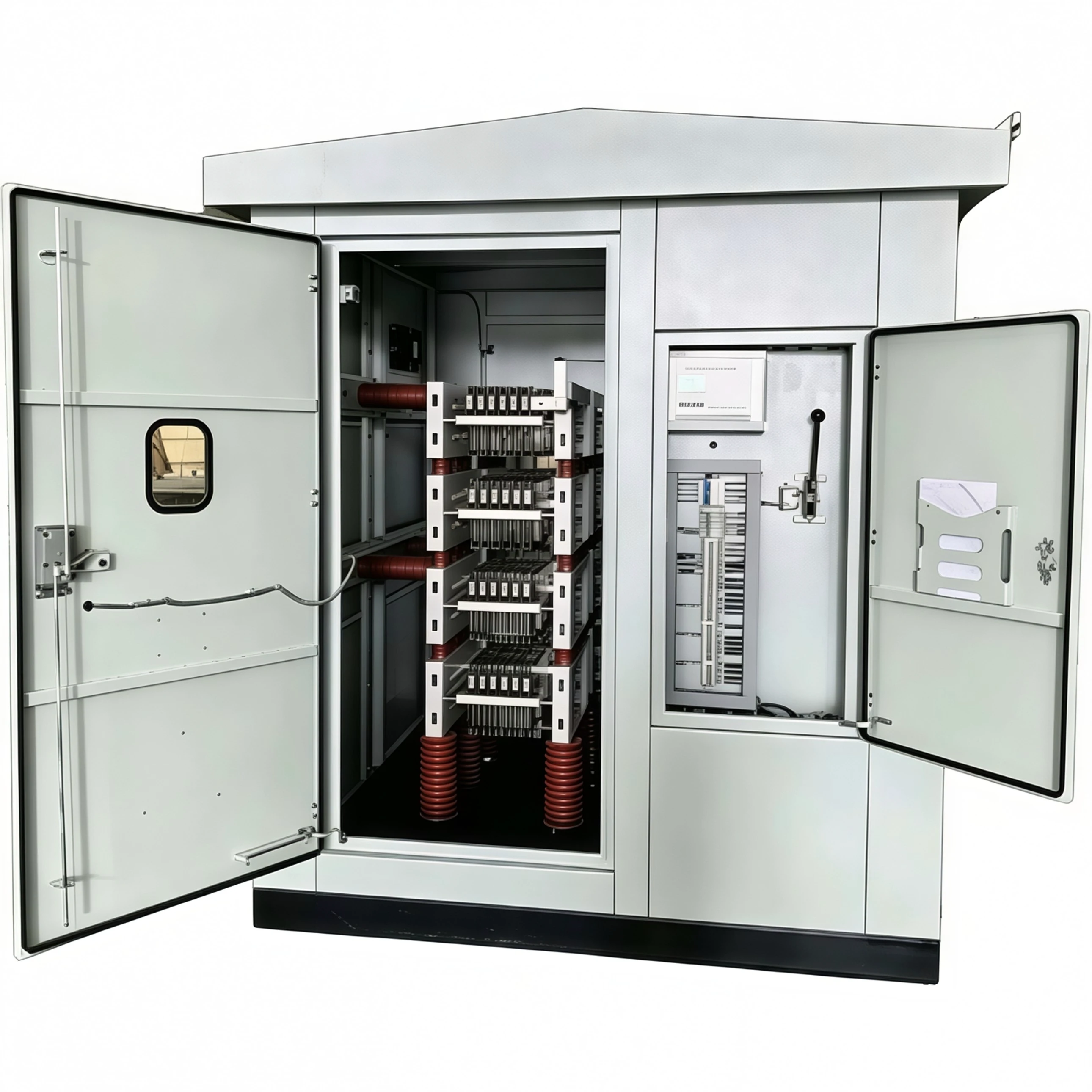
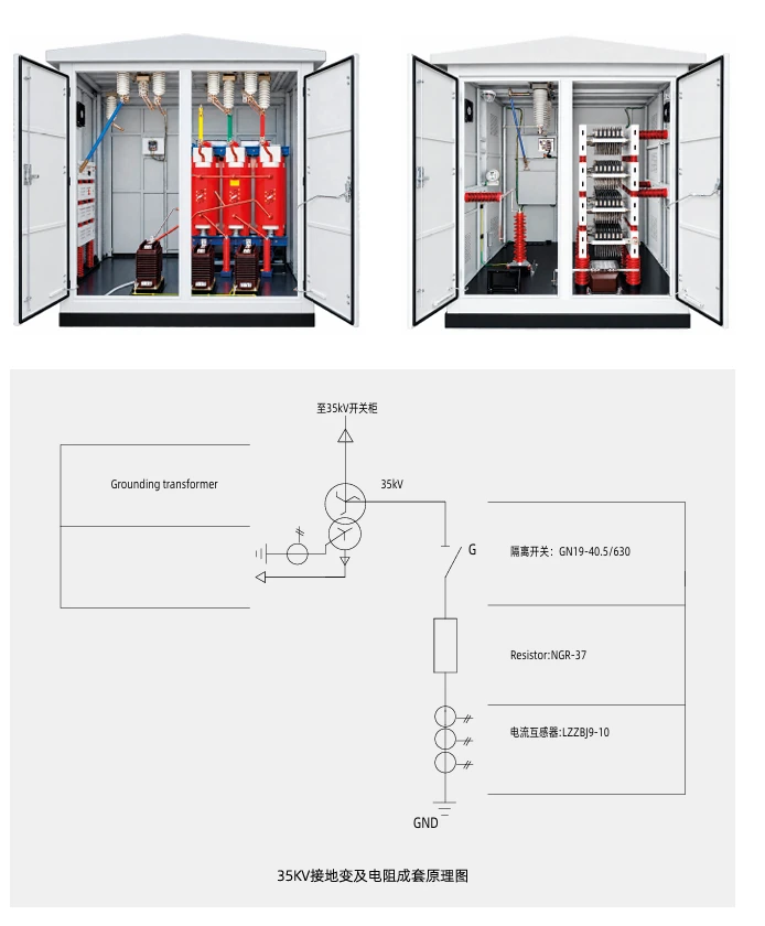
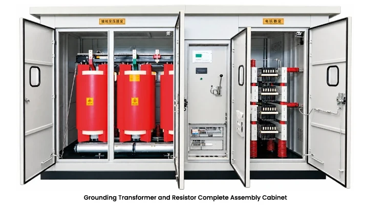
The products can be professionally customized or com-bined according to different working conditions, differentwiring methods, or customer requirements. Standardconfigurations include enclosure, resistance elements,current transformers, etc.; optional configurations in-clude grounding transformers, disconnect switches, in-telligent monitoring devices, etc
| Applicable voltage | 0.4KV~66KV |
| Allowable current | 3A~2000A(selected according to cus- tomer requirements) |
| Nominal resistance | 0.010~15000(selected according to customer requirements) |
| Allowable current duration | 0 s,30 s,60 s,10 min,or continuous oper-ation |
| Line entry/exit method | Bottom in/bottom out,top in/bottom out (customised as per customer require- ments) |
| Allowable temperature rise | 760℃ for 10 s,30 s,or 60 s durations |
| 610℃ for 10 min duration | |
| 385℃ for continuous operation | |
| Degree of protection | IP2X-IP5X,suitable for both indoor and outdoor use |
| Auxiliary configurations | optional disconnector(isolating switch), intelligent monitoring device,etc |
high cost-performance ratio.
| DL/T7802001 | Neutral Grounding Resistor for Power Dis- tribution Systems |
| GB/T 12342012 | High-Resistance Electric Heating Alloys |
| DL/T 6201997 | Overvoltage Protection and Insulation Coordination for AC Electrical Installa- tions |
| DL/T 5932016 | Common Technical Requirements for High-Voltage Switchgear and Control- gear Standards |
| GB 311.12012 | Insulation Coordination for High-Voltage Power Transmission and Transformation Equipment |
| GB/T 10222011 | Common Technical Specifications for High-Voltage Switchgear and Control- gear |
| GB/T 16927.22011 | High-Voltage Test Techniques |
| GB 42082017 | Degrees of Protection Provided by Enclo-sures(IP Code) |
| IEEE Std 321972 | Requirements,Terminology,and Tests for Neutral Grounding Devices |
| IEEE Std C37.101-2006 | Guide for Generator Ground Protection |
| IEEE Std C62.92.2-3-1993 | Guide for Neutral Grounding in Generator Auxiliary Systems |
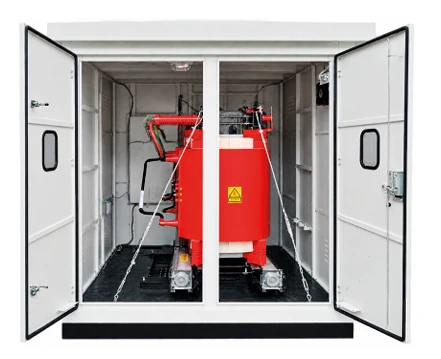
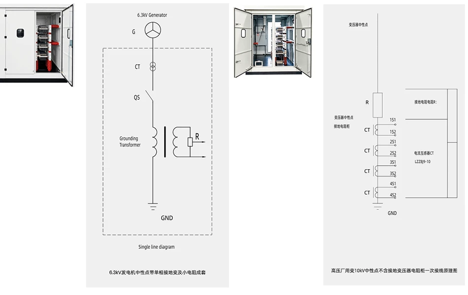
| HL-NGR Series Typical Neutral Grounding Resistor Equ | ipment Technical Data sheet | ||||||
| Model | System Rated Volt- age(kv) |
Resistor Rated Volt- age(kv) |
Short time Allowable Current(A) |
hort time Duration (s) |
Nominal Resistance (2) |
overall Dimensions W×D×H(mm) |
Weight (kg) |
| HL-NGR-6.3/100-10 | 6.3 | 3.64 | 100 | 10 | 36.40 | 920*1050*1650 | 450 |
| HL-NGR-6.3/200-10 | 6.3 | 3.64 | 200 | 10 | 18.20 | 500 | |
| HL-NGR-6.3/400-10 | 6.3 | 3.64 | 400 | 10 | 9.09 | 500 | |
| HL-NGR-6.3/600-10 | 6.3 | 3.64 | 600 | 10 | 6.06 | 500 | |
| HL-NGR-6.3/1000-10 | 6.3 | 3.64 | 1000 | 10 | 3.64 | 500 | |
| HL-NGR-10/100-10 | 10.0 | 5.77 | 100 | 10 | 57.70 | 1000*1400*1800 | 500 |
| HL-NGR-10/200-10 | 10.0 | 5.77 | 200 | 10 | 28.90 | 550 | |
| HL-NGR-10/400-10 | 10.0 | 5.77 | 400 | 10 | 14.50 | 550 | |
| HL-NGR-10/600-10 | 10.0 | 5.77 | 600 | 10 | 9.62 | 550 | |
| HL-NGR-10/1000-10 | 10.0 | 5.77 | 1000 | 10 | 5.77 | 550 | |
| HL-NGR-20/400-10 | 20.0 | 1.50 | 400 | 10 | 28.90 | 1400*1800*2400 1600*2600*2500 |
1,250 |
| HL-NGR-20/600-10 | 20.0 | 1.50 | 600 | 10 | 19.20 | 1,250 | |
| HL-NGR-35/200-10 | 35.0 | 20.30 | 200 | 10 | 101.00 | 2,000 | |
| HL-NGR-35/400-10 | 35.0 | 20.20 | 400 | 10 | 50.50 | 2,000 | |
| HL-NGR-35/600-10 | 35.0 | 20.20 | 600 | 10 | 33.70 | 2,000 | |
| HL-NGR-35/1000-10 | 35.0 | 20.20 | 1000 | 10 | 20.20 | 2,000 | |
| HL-NGR-35/1300-10 | 35.0 | 20.20 | 1300 | 10 | 15.50 | 2,500 | |
| HL-NGR-35/2000-10 | 35.0 | 20.20 | 2000 | 10 | 10.10 | 2,500 | |
| Technical Data Sheet-HL-NGR Series Generator Neutral High Resistance Grounding Resistor Equipment |
|||||||||
| Generator Capacity(MW) | 100/125 | ||||||||
| Generator Rated Voltage (kV) | 10.50 | 13.80 | 15.75 | 18.00 | 20.00 | 20.00 | 24.00 | 24.00 | 27.00 |
| Estimated Single Phase to Ground Current of the Circuit |
|||||||||
| Capacitive Current(A) | 4 | 5 | 6 | 8 | 10 | ||||
| Single Phase Grounding Transformer Primary Voltage(kV) |
0.5/ √3 | 13.8/ √3 | 15.75/ √3 | 18/ √3 | 20/ √3 | 20/ √3 | 24/ √3 | 24/ √3 | 27/ √3 |
| Single Phase Grounding Transformer Secondary Voltage(kv) |
0.22 | 0.22 | 0.22 | 0.22 | 0.22 | ||||
| Single Phase Grounding Transformer Rated Capacity(KVA) |
30 | 30 | 50 | 50 | 63 | ||||
| Secondary Side Resistance Value(Q) | 10 | 0.8 | 0.5 | 0.4 | 0.3 | ||||
| Grounding Protection Secondary Side Extracted Voltage(kv) |
0.1 | 0.1 | 0.1 | 0.1 | 0.1 | ||||
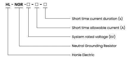
When placing an order for the neutral grounding resistor equipment,the customer shall provide the following information relating to the
product:

Escort Your Power Quality and Safety with Our Products
Contact UsGET A QUOTE