How does a voltage regulator work and what are its internal components?

 Site Editor
What is a voltage regulator?
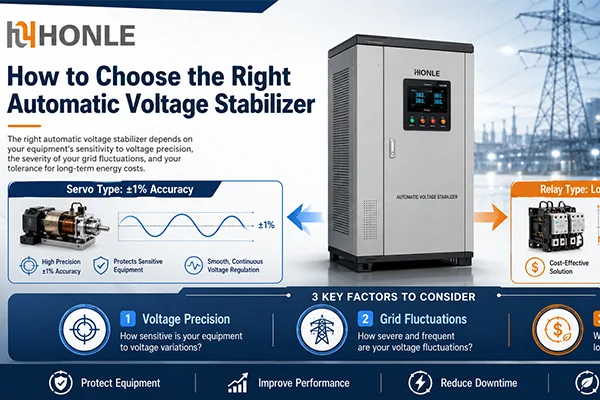
When we need to know how the voltage stabilizer work, we need to understand what the voltage stabilizer is. Voltage stabilizer is a electrical device which is designed to deliver constant output voltage regardless of the input supply(It is important to note that it doesn’t protect appliance from sudden load change or internal fault of appliances). Basically it protects appliances from over-voltages and under-voltages.

It is also called as automatic voltage regulator (AVR). Voltage stabilizers are preferred for costly and precious electrical equipments to protect them from harmful low/high voltage fluctuations. Some of these equipments are air conditioners, offset printing machines, laboratory equipments, industrial machines, and medical apparatus etc.
Voltage stabilizers regulate the fluctuating input voltage before it could be fed to the load (or equipment which is sensitive to voltage variations). The output voltage from the stabilizer will stay in the range of 220V or 230V in case of single phase supply and 380V or 400V in case of three phase supply, within given fluctuating range of input voltage. This regulation is carried by buck and boost operations performed by internal circuitry.
The working principle of voltage regulators
In a voltage stabilizer, voltage correction from over and under voltage conditions is performed through two essential operations, namely boost and buck operations. These operations can be carried manually by switches or automatically through electronic circuitry. During under voltage condition, boost operation increases the voltage to a rated level while buck operation reduces the voltage level during over voltage condition. The concept of stabilization involves in adding or subtracting the voltage to and from the mains supply. For performing such task stabilizer uses a transformer which is connected in different configurations with switching relays. Some stabilizers use a transformer with taps on winding to provide different voltage corrections.

Above figure illustrates the boosting configuration in which the polarity of the secondary winding is oriented in such a way that its voltage is directly added to the primary voltage.
Therefore, in case of under voltage condition, transformer (whether it can be tap changing or auto-transformer) is switched by the relays or solid state switches such that additional volts are appended to the input voltage.

In above figure, transformer is connected in buck configuration, where the polarity of secondary coil is oriented in such a way that its voltage subtracts from the primary voltage. The switching circuit shifts the connection to the load to this configuration during over voltage condition.

And final circuitry look as this is a two stage voltage stabilizer which uses two relays to provide constant AC supply to the load during over-voltage and under voltage conditions. By switching the relays, buck and boost operations for two specific voltage fluctuations (one is under-voltage, for instance, say 200V and another for over-voltage, say 250V) can be performed.
What are voltage regulators components inside?
- Buck-boost transformer
- Voltage comparator circuit
- Auxiliary transformer for power supply to electronic circuit.
- Optional- Power on time delay circuit.
There are huge varieties of automatic voltage regulators are available in today’s market. These can be single or three-phase units as required by the type of application and capacity (KVA) needed. Three-phase stabilizers come in two versions as balanced load models and unbalanced load models.
The circuit of a voltage stabilizer basically consists of a voltage sensor. It is configured to detect the rise or fall of the AC mains voltage to dangerous levels. As soon it senses a risky input voltage, it immediately energizes the relays connected to it. These relays in turn swaps and switches the appropriate winding terminals of the auto transformer to correct and stabilize the output voltage. Thus the appliance which is connected to the output of the voltage stabilizer circuit always receives a safe, tolerable voltage and is able to function reliably, irrespective of the fluctuating input voltages.